01
View
Publication
WELDING SYMBOLS
Total Views
14
Total Downloads
3
Published
03 Oct 2026
Last Updated
03 Oct 2026
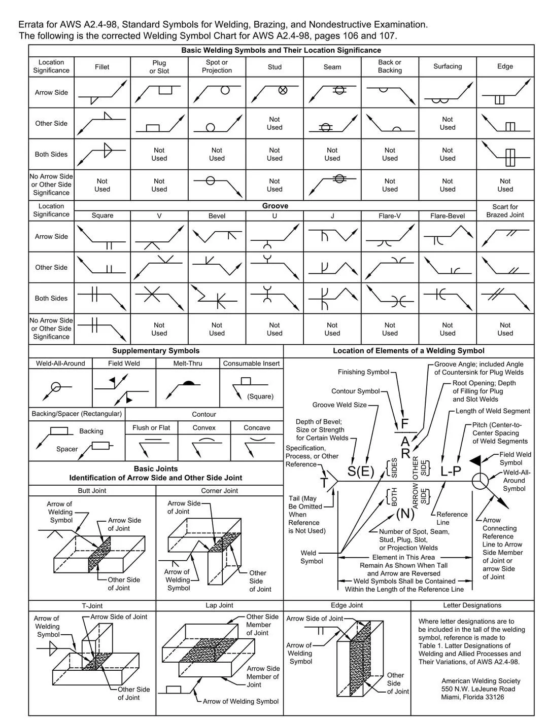
What Are Welding Blueprint Symbols?
Welding blueprint symbols are used as a means of communication between a designer, such as a shop foreman, welding engineer or supervisor, and a welder. Essentially, they are a set of symbols used as a shorthand code for describing the type of weld, its size and other processing and finishing information. They appear on engineering and fabrication drawings, which the welder will refer to in order to create their weld.
Welders live by the 1/16th rule—meaning their welds can be larger or smaller than what is specified by no more than 1/16th of an inch. Precision is key in this industry, so it’s important for welders to understand blueprints and how to follow them to create welds that are up to standard.
Before starting their weld, welders will typically look at a Welding Procedure Specification (WPS), which is a document that gives direction to the welder by providing information such as material thickness, the general position the part needs to be welded in, the electrodes to use and more. From here, the welder will look at the welding blueprint, which contains weld symbols, specific measurements and other information needed to complete the task. These blueprints come in different forms, such as isometric, orthographic and 3D.
Comments